Experimenting with 6502 assembly code, coloring the bitmap display. Logical Shift Right, Arithmetic Shift Left, and more…..
Introduction
After analysis, optimization, modifications…. It is time to experiment with some new instructions, learn new instructions and understand what shifts are, and how they affect the program!
Experiment 1: tya instruction
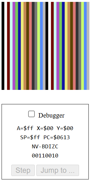
What does adding the tya instruction inside the loop, do? Well, looks like it results in some vertical lines. But why? That is because, tya stands for “Transfer Index Y To Accumulator”. Meaning, the accumulator is populated with the value of Y, and therefore the value of Y is what gets written on every page’s memory.
ldy #$00     ; set y index

loop:
    tya ; transfer y to accum
    sta $0200,y
    sta $0300,y
    sta $0400,y
    sta $0500,y
    iny ; increment y index
    bne loop
There are 16 possible colors, ranging from $0 (black) to $f (light grey), but there are 32 columns. But as we can see, the pattern repeats itself in the middle. This is because the lowest 4 bits of each byte is what gets selected to display the color. Which means, even when the value is higher than 16, only the lowest 4 bits are considered, and a valid color gets displayed, in vertical lines.
Experiment 2: Logical Shift Right, lsr
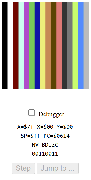
When we add the lsr instruction below tya, the result is similar to the last, featuring thicker vertical lines this time – 16 of them. What does this mean? lsr stands for “Logical Shift Right”, which introduces a new concept: shift.
ldy #$00     ; set y index

loop:
    tya ; transfer y to accum
    lsr ; logical shift right
    sta $0200,y
    sta $0300,y
    sta $0400,y
    sta $0500,y
    iny ; increment y index
    bne loop
Shift
A Logical Shift involves shifting the entire binary sequence to the right or left, and adding a zero to the missing, leftmost or rightmost bit of an 8-bit value. It also affects the carry flag, setting it to whatever value got pushed out. Shifting right, essentially divides by 2.
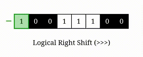
Here is an illustration of what happens when lsr is called, on the accumulator. see more.
So how does that explain the result? lsr doesn’t actually change the value at the Y register, only the value of the accumulator – which gets written on the pixel. While Y increments consistently, calling lsr after incrementing the accumulator, forces the value to reset-back every other time, causing actual change in the accum, only every 2 iterations.
Here is an example of how the Y and Accumulator registers change over time, starting from somewhere in the middle – when Y is $11 (on the 17th iteration).
Y, A Before: 00010001 ($11)
A After: 00001000 ($08) => "Orange"

Y, A Before: 00010010 ($12)
A After: 00001001 ($09) => "Brown"

Y, A Before: 00010011 ($13)
A After: 00001001 ($09) => "Brown"

Y, A Before: 00010100 ($14)
A After: 00001010 ($0a) => "Light Red"

Y, A Before: 00010101 ($15)
A After: 00001010 ($0a) => "Light Red"
We can see that even though the colors of Y go chronologically, 1 by 1, A is changing. The lsr instruction causes it to repeat each color twice, because the result of lsr brings it back by 1 operation. The “low nibble” (last 4 bits of a number) coorespond to colors.
Experiment 3: Multiple Shifts, lsr
Repeating the lsr instruction, actually results in something a bit unexpected. Here are the results when it is repeated 3, 4 and 6 times, respectively:
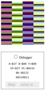
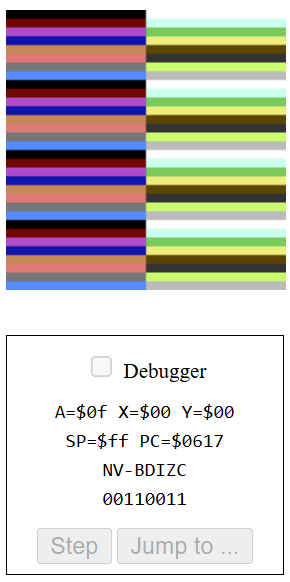
Analyzing 3 Repetitions of lsr
We can deduce, even visually – by noticing the division into 4 parts (32 / 4 = 8), that the color changes every 8 bits, or every 8 iterations. This is because the value is effectively divided by 2, 3 times, so the color changes every 23 bits.
Y, A Before: 00000111 ($07)
A After 3xlsr: 00000000 ($00) => "Black"

Y, A Before: 00001000 ($08)
A After 3xlsr: 00000001 ($01) => "White"

Y, A Before: 00001001 ($09)
A After 3xlsr: 00000001 ($01) => "White"

...... after 16 iterations (Y = $10)

Y, A Before: 00010000 ($10)
A After 3xlsr: 00000010 ($02) => "Red"
Analyzing 4 Repetitions of lsr
Let’s see if the same rule applies to 4 repetitions! Visually, it is clear that the color changes every (32 / 2) 16 bits. 24 = 16, which explains the result – the value gets divided by 2, 4 times, and therefore only increments when reaching a value that is a multiple of 16 (0, 16, 32, 48, 64…..)
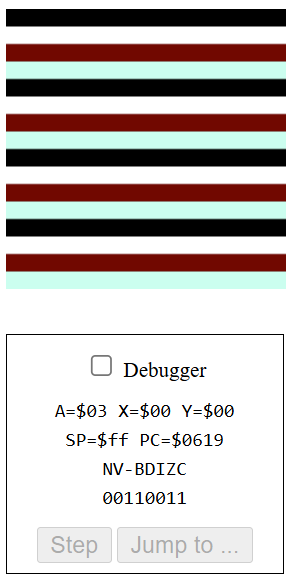
Analyzing 6 Repetitions of lsr
Again, in the 6 repetitions example, we can see the color changes every 2 rows, 64 bits. This works because 26 = 64. Therefore, the color would only change when reaching a multiple of 64 (128, 192, 256….)
General Rule: n Repetitions.
Given n represents the number of times a Logical Shift Right lsr is applied to X, the value in decimal, the new decimal value would be:
Xnew = X / 2n
In other words, when applying to our bitmap example, the color would change every 2n bits, or pixels.
Experiment 2: Arithmetic Shift Left, asl
Coming soon!!!!
Conclusion
These seemingly simple, but challenging experiments, introduced new concepts, such as logical and arithmetic shifts. Although there are a few more experiments remaining, which I will try to get back to, these new – and old – concepts are definitely becoming more clear, through practice, trial and error. Next I will get to explore longer, more complex code, and eventually even create my own program in assembly!
Leave a Reply