Introduction
Previously, I got to experiment with analyzing and modifying assembly code for the 6502 processor, and learned about common instructions, and what they do. Now, it is time to experiment with more complex logic, flow and mathematical operations.
I was provided with an implementation of a subroutine DRAW, which draws a certain 5×5 image to the bitmap screen, at given coordinates. The tester loop that was provided with it, creates an illusion of a diagonally moving shape, by drawing and erasing, and redrawing at a different position.
The current, inital tester code moves the shape diagonally until it “hits” a border (the leftmost wall, 32 bits), and then resets it back to the beginning, meaning the shape only moves 1 way.
The Goal: Adjust the code to make the shape “bounce” back when hitting a border, by changing its direction.
Analyzing Initial Code
DRAW Subroutine
Here is theDRAW subroutine, which I got from the course website. It draws an image onto the bitmap display.
; ==========================================
;
; DRAW :: Subroutine to draw an image on
; the bitmapped display
;
; Entry conditions:
; A - location in zero page of:
; a pointer to the image (2 bytes)
; followed by the image width (1 byte)
; followed by the image height (1 byte)
; X - horizontal location to put the image
; Y - vertical location to put the image
;
; Exit conditions:
; All registers are undefined
;
; Zero-page memory locations
define IMGPTR $A0
define IMGPTRH $A1
define IMGWIDTH $A2
define IMGHEIGHT $A3
define SCRPTR $A4
define SCRPTRH $A5
define SCRX $A6
define SCRY $A7
DRAW:
; SAVE THE X AND Y REG VALUES
STY SCRY
STX SCRX
; GET THE DATA STRUCTURE
TAY
LDA $0000,Y
STA IMGPTR
LDA $0001,Y
STA IMGPTRH
LDA $0002,Y
STA IMGWIDTH
LDA $0003,Y
STA IMGHEIGHT
; CALCULATE THE START OF THE IMAGE ON
; SCREEN AND PLACE IN SCRPTRH
;
; THIS IS $0200 (START OF SCREEN) +
; SCRX + SCRY * 32
;
; WE'LL DO THE MULTIPLICATION FIRST
; START BY PLACING SCRY INTO SCRPTR
LDA #$00
STA SCRPTRH
LDA SCRY
STA SCRPTR
; NOW DO 5 LEFT SHIFTS TO MULTIPLY BY 32
LDY #$05 ; NUMBER OF SHIFTS
MULT:
ASL SCRPTR ; PERFORM 16-BIT LEFT SHIFT
ROL SCRPTRH
DEY
BNE MULT
; NOW ADD THE X VALUE
LDA SCRX
CLC
ADC SCRPTR
STA SCRPTR
LDA #$00
ADC SCRPTRH
STA SCRPTRH
; NOW ADD THE SCREEN BASE ADDRESS OF $0200
; SINCE THE LOW BYTE IS $00 WE CAN IGNORE IT
LDA #$02
CLC
ADC SCRPTRH
STA SCRPTRH
; NOTE WE COULD HAVE DONE TWO: INC SCRPTRH
; NOW WE HAVE A POINTER TO THE IMAGE IN MEM
; COPY A ROW OF IMAGE DATA
COPYROW:
LDY #$00
ROWLOOP:
LDA (IMGPTR),Y
STA (SCRPTR),Y
INY
CPY IMGWIDTH
BNE ROWLOOP
; NOW WE NEED TO ADVANCE TO THE NEXT ROW
; ADD IMGWIDTH TO THE IMGPTR
LDA IMGWIDTH
CLC
ADC IMGPTR
STA IMGPTR
LDA #$00
ADC IMGPTRH
STA IMGPTRH
; ADD 32 TO THE SCRPTR
LDA #32
CLC
ADC SCRPTR
STA SCRPTR
LDA #$00
ADC SCRPTRH
STA SCRPTRH
; DECREMENT THE LINE COUNT AND SEE IF WE'RE
; DONE
DEC IMGHEIGHT
BNE COPYROW
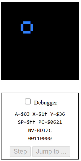
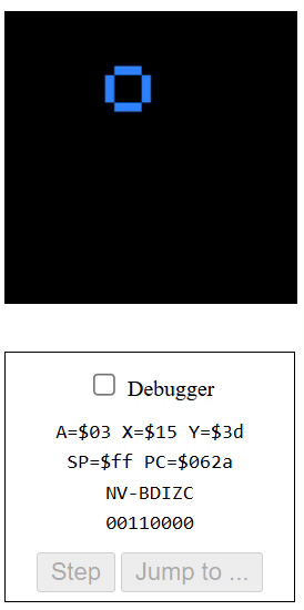
RTS5×5 Pixel Images
These are the pixel images for the shapes that were provided. The black square is used to erase the current shape, so that it can be moved cleanly to the next position.
; Image of a blue "O" on black background
G_O:
DCB $00,$0e,$0e,$0e,$00
DCB $0e,$00,$00,$00,$0e
DCB $0e,$00,$00,$00,$0e
DCB $0e,$00,$00,$00,$0e
DCB $00,$0e,$0e,$0e,$00

; Image of a yellow "X" on a black background
G_X:
DCB $07,$00,$00,$00,$07
DCB $00,$07,$00,$07,$00
DCB $00,$00,$07,$00,$00
DCB $00,$07,$00,$07,$00
DCB $07,$00,$00,$00,$07

; Image of a black square
G_BLANK:
DCB $00,$00,$00,$00,$00
DCB $00,$00,$00,$00,$00
DCB $00,$00,$00,$00,$00
DCB $00,$00,$00,$00,$00
DCB $00,$00,$00,$00,$00
Tester Loop
This draw subroutine was invoked from the main-loop below, to draw the shape on the screen at a given position, and then (after a certain delay), draw the black square – effectively erasing it from the screen, then redrawing the shape at a different position, etc… This would create the animation of the moving shape, gliding in a diagonal.
;
; draw-image-subroutine.6502
;
; This is a routine that can place an arbitrary
; rectangular image on to the screen at given
; coordinates.
;
; Chris Tyler 2024-09-17
; Licensed under GPLv2+
;

;
; The subroutine is below starting at the
; label "DRAW:"
;

; Test code for our subroutine
; Moves an image diagonally across the screen

; Zero-page variables
define XPOS $20
define YPOS $21


START:

; Set up the width and height elements of the data structure
  LDA #$05
  STA $12       ; IMAGE WIDTH
  STA $13       ; IMAGE HEIGHT

; Set initial position X=Y=0
  LDA #$00
  STA XPOS
  STA YPOS

; Main loop for diagonal animation
MAINLOOP:

  ; Set pointer to the image
  ; Use G_O or G_X as desired
  ; The syntax #<LABEL returns the low byte of LABEL
  ; The syntax #>LABEL returns the high byte of LABEL

  LDA #<G_O
  STA $10
  LDA #>G_O
  STA $11

  ; Place the image on the screen
  LDA #$10  ; Address in zeropage of the data structure
  LDX XPOS  ; X position
  LDY YPOS  ; Y position
  JSR DRAW  ; Call the subroutine

  ; Delay to show the image
  LDY #$00
  LDX #$50
DELAY:
  DEY
  BNE DELAY
  DEX
  BNE DELAY

  ; Set pointer to the blank graphic
  LDA #<G_BLANK
  STA $10
  LDA #>G_BLANK
  STA $11

  ; Draw the blank graphic to clear the old image
  LDA #$10 ; LOCATION OF DATA STRUCTURE
  LDX XPOS
  LDY YPOS
  JSR DRAW

  ; Increment the position
  INC XPOS
  INC YPOS

  ; Continue for 29 frames of animation
  LDA #28
  CMP XPOS
  BNE MAINLOOP

  ; Repeat infinitely
  JMP START
Bouncing Graphic
To achieve the bouncing graphic affect, we must modify the main code to consider direction, since the shape could now travel across the screen up, down, left and right. In addition to simply considering the direction, there must be logic implemented to changing the direction, and applying it to the position.
Storing Direction
First we need to define where the direction value will be tracked. Here we defined it at memory location #$22 and #$23, next to the X & Y positions. These locations will be holding the current respective direction, -1 signifying left or up, and 1 signifying right or down. The initial direction would be set to 1, for simplicity.
We must also choose different X & Y positions to start, so that the shape has the chance to bounce on all the borders before looping around, to test the code better.
define XPOS $20
define YPOS $21
define XDIR $22
define YDIR $23

...

; Set initial positions (different)
  LDA #$06
  STA XPOS
  LDA #$01
  STA YPOS

; Set initial directions (positive)
  LDA #$01
  STA XDIR
  STA YDIR
Incrementing Positions
The original code simply increments XPOS & YPOS until they cross the boundary, and then resets the animation. Since these values now need to increment or decrement, depending on the value of the _DIR variable, we must change that part of the code to support this new requirement.
  LDA XPOS  ; Load XPOS into accumulator
  CLC       ; Clear carry for consistency
  ADC XDIR  ; Add XDIR value to accumulator
  STA XPOS  ; Store updated value into XPOS

  LDA YPOS
  CLC
  ADC YDIR
  STA YPOS
Changing Direction
There are a few ways to implement changing the direction, once any border is reached. The simplest way is to set the XDIR explicitly, depending on which boundary was reached.
MAKE_XDIR_POS:
  LDA #01
  STA XDIR

MAKE_XDIR_NEG:
  LDA #ff
  STA XDIR

MAKE_YDIR_POS:

MAKE_YDIR_NEG:
Putting the control instructions aside, this way might be simpler and even more efficient, with very minimal lines of code. Of course in the real implementation, there would be branching instructions and even comparisons within each of these branches, but simply put – changing the value directly is a good option.
However, there are aspects of this approach that might not work in the future, for example if the direction magnitude is variable, and can be more than 1, the code would be a lot harder to change to support that. In addition to that, there are several repeating lines of code that can otherwise be avoided. The second method can be used to flip any number to its compliment sign, and abstracts that logic so it can be reused.
FLIP_X:	    ; Flip XDIR
  LDA XDIR  ; Load XPOS into accum.
  EOR #$FF  ; Flip bits (0001 => 1110)
  CLC
  ADC #$01  ; Add 1 to compensate for negation
  STA XDIR  ; Store updated direction


FLIP_Y:     ; Flip YDIR
  ...
Using EOR, we can flip the bits of the current _DIR value, which effectively changes it from positive to negative, and vice versa. The only issue is that the flip subtracts 1 from the value, which can result in undefined behavior.
EOR – Exclusive OR (XOR)
EOR #$FF achieves this result by comparing each 2 bits. For every two bits:
- If bits are different – result is
1 - If bits are the same – result is
0 #$FFis chosen because it forces all 0’s to turn into 1’s, and vice versa.
; Example: flipping 1
;      XDIR = 0000 0001 (decimal 1)
;      #$FF = 1111 1111
; EOR #$FF => 1111 1110 (sign. dec -2)

; Example: flipping 5
;      XDIR = 0000 0101 (dec 5)
;      #$FF = 1111 1111
; EOR #$FF => 1111 1010 (sign. dec -6)
As we can see, the number is being flipped, but the value is slightly off – by 1. That is why we do the ADC #$01 after the operation, to account for this occurence.
In reality, this logic can be further abstracted, which impacts performance but improves readability and maintainability:
FLIP_X:           ; Flip XDIR direction
  LDA XDIR
  JSR FLIP_ACCUM  ; Flip value on accum.
  STA XDIR

FLIP_Y:           ; Flip YDIR direction
  LDA YDIR
  JSR FLIP_ACCUM
  STA YDIR

; Subroutine for flipping the value @ the accumulator
FLIP_ACCUM:
  EOR #$FF        ; Flip bits (0001 => 1110)
  CLC
  ADC #$01        ; Add 1 to compensate for negation
  RTS
Checking Boundaries – Flow
To check if any border was reached, I will load the _POS onto the accumulator, then subtract a value from it, and branch on a condition. There are similar steps that are repeated for both X and Y:
- Left/Top boundaries
POS ≤ 0: reached if value is 0 or lowerCMP #$01performs POS – 1, and sets the negative flag. Negative means boundary reached!- Within boundary (15): 15 – 1 = 14
- Exact boundary (0): 0 – 1 = -1
- Beyond boundary (-3): -3 – 1 = -4
BMI FLIPgoes to flip when negative result, when boundary reached.
- Right/Bottom boundaries
POS ≥ 27CMP #$1Bperforms POS – 27, and sets negative flag. Negative means POS is within the boundary!- Within boundary (9): 9 – 27 = -18
- Exact boundary (27): 27 – 27 = 0
- Beyond boundary (31): 31 – 27 = -4
BMI SKIPskips flipping if negative result, otherwise continues to the next code – which is the flip. Thus “diverting” normal values to skip the flip.
CHECK_X:    ; Check X boundary (left or right)
  LDA XPOS

  CMP #$01    ; Left (if XPOS <= 0): perform XPOS - 1
  BMI FLIP_X  ; FLIP_X if border (neg flag), else cont.

  CMP #$1B    ; Right (if XPOS >= 27): perform XPOS - 27
  BMI CHECK_Y ; CHECK_Y if not reached border, else cont.

FLIP_X:	    ; Flip XDIR direction
  LDA XDIR
  JSR FLIP_ACCUM
  STA XDIR

CHECK_Y:    ; Check Y boundary (top or bottom)
  LDA YPOS

  CMP #$01    ; Top (if YPOS <= 0): perform YPOS - 1
  BMI FLIP_Y  ; FLIP_Y if border (neg flag), else cont.

  CMP #$1B    ; Bottom (if YPOS >= 27): perform YPOS - 27
  BMI SKIP_Y  ; SKIP_Y if not reached border, else cont.

FLIP_Y:	    ; Flip YDIR direction
  LDA YDIR
  JSR FLIP_ACCUM
  STA YDIR

SKIP_Y:     ; Jump back to main loop
  JMP MAINLOOP
The flow goes as follows:
- Check left boundary. If boundary reached, go to step 3. Else continue.
- Check right boundary. If boundary reached, continue. Else go to 4
- Flip X direction (flip the sign). Continue.
- Check top boundary. If boundary reached, go to step 6. Else continue.
- Check bottom boundary. If reached, continue. Else go to 7.
- Flip Y direction (flip the sign). Continue.
- Jump back to
MAINLOOP.
Result & Conclusion
- The final result features an infinite graphic animation of the shape, bouncing from border to border, changing direction.
- Common or repeating functionalities, such as flipping direction (eg.
FLIP_ACCUM), were abstracted for readability and maintainability, at a small performance cost. - Flipping functionality supports different values for direction since explicit value setting was avoided, improving scalability.
- Download the full source code here:
Leave a Reply