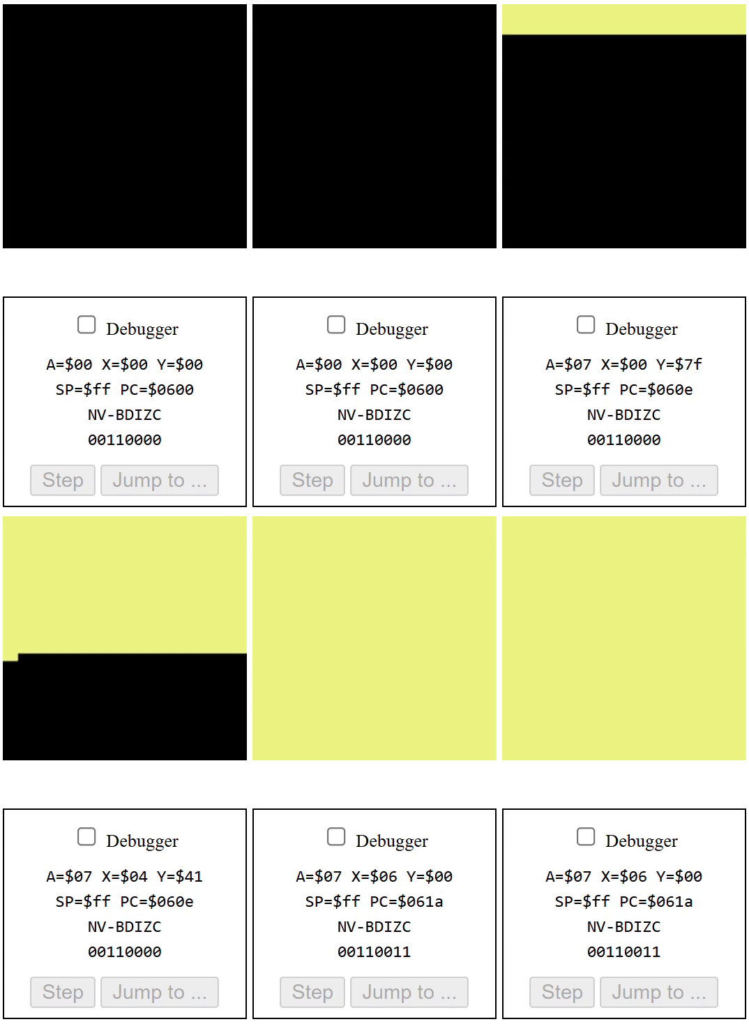
Analyzing code objectives, run-time and memory complexity.
Introduction
A few weeks ago, I enrolled in the Software Portability & Optimization course at my college. We got familiar with the structures and components of a CPU (Status Register, Accumulator, Program Counter, Stack…) in order to understand how assembly code works, and what it means. Modern CPU’s are incredibly complex, so throughout the course we will focus on the 6502 microprocessor, as it is relatively simple, and well documented.
Code Functionallity
For this lab, we were provided with the following lines of code, which we used to run in the online 6502 emulator.
lda #$00     ; set ptr in adrs $40, point to $0200
sta $40	     ; ... low byte ($00) goes in adrs $40
lda #$02
sta $41	     ; ... high byte ($02) goes in adrs $41
lda #$07     ; colour number
ldy #$00     ; set index to 0

loop: sta ($40),y ; set pixel colour at the adrs (ptr)+Y
      iny         ; increment index
      bne loop    ; continue until done page (256 px)

      inc $41	  ; increment the page
      ldx $41	  ; get the current page number
      cpx #$06	  ; compare with 6
      bne loop	  ; continue until done all pages
taken from the 6502 emulator.
Although this code seems confusing, after some analysis of the instructions, I have formed some conclusions:
- The objective is to color all pixels on the screen, into a single color.
- There are 256 pixels on each page.
- There are 4 pages of pixels on the screen (each page is a horizontal slice).
- There is an inner loop, coloring each pixel on the page.
- There is an outer loop, coloring each page.
Performance Analysis
To analyze the run-time and memory usage, I used the 6502 Reference to derive the number of cycles, or operations, that each instruction “takes”.
Alternative Cycles & Counts
The Alternative Cycles and Counts, are specifically relevant when using branching, or conditional actions. What it essentially means, is that instructions like BNE (Branch if not zero), have different performance when their condition evaluates to True, or False.
For example, if our loop executes a total of n=4 times, 3 times of those 4 (n-1), the BNE will evaluate to True (when result is not zero), and jump back to the beginning of the loop. In situations like these, the documentation states 3 cycles (the additional jump adds a cycle). However, in cases where the end of the loop is reached, (when the result evaluates to 0), which executes once in the loop, the instruction only takes 2 cycles. Therefore we get the formula:
# Main (when loop exits, branch is not taken):
Cycles = 2
Count = 1 (exits once).
=> 2 x 1 = 2

# Alt (when loop continues, branch is taken):
Cycles = 2 + 1 = 3 ( +1 for branch is taken)
Count = n - 1 (where n is the number of times the loop executes)
=> 3 x (n-1)| Cycles | Count | Alt-Cycles | Alt-Count | Total | |
|---|---|---|---|---|---|
| LDA #$00 | 2 | 1 | 2 | ||
| STA $40 | 3 | 1 | 3 | ||
| LDA #$02 | 2 | 1 | 2 | ||
| STA $41 | 3 | 1 | 3 | ||
| LDA #$07 | 2 | 1 | 2 | ||
| LDY #$00 | 2 | 1 | 2 | ||
| LOOP STA ($40), Y | 6 | 256(4) | 6144 | ||
| INY | 2 | 256(4) | 2048 | ||
| BNE LOOP | 2 | 1(4) | 3 | 255(4) | 3068 |
| INC $41 | 5 | 4 | 20 | ||
| LDX $41 | 3 | 4 | 12 | ||
| CPX #$06 | 2 | 4 | 8 | ||
| BNE LOOP | 2 | 1 | 3 | 3 | 11 |
Total Cycles: 11325
Clock Speed: 1 MHz
Cycle Time: 0.000001 Seconds
Execution Time: 0.011325 Seconds
The code takes
11.325 mSto execute, at 1 MHz clock speed.
Memory Usage Analysis
To calculate the “total memory usage for the program code plus any pointers or variables”, I will first analyze the code to see how many, and what kind of variables and pointers were used, and then use the 6502 Reference to determine the memory usage of each instruction.
In lines 2 and 4, we are using the STA command, to load the low and high byte of the address of the first page to print on (#$0200). This 1 pointer takes up 2 bytes:
- Low Byte, $#00, is stored in address $40.
- High Byte, $#02, is stored in address $41
| Instruction | Memory (Bytes) |
|---|---|
| LDA #$00 | 2 |
| STA $40 | 2 |
| LDA #$02 | 2 |
| STA $41 | 2 |
| LDA #$07 | 2 |
| LDY #$00 | 2 |
| LOOP STA ($40), Y | 2 |
| INY | 1 |
| BNE LOOP | 2 |
| INC $41 | 2 |
| LDX $41 | 2 |
| CPX #$06 | 2 |
| BNE LOOP | 2 |
The total memory usage, including the instructions and the pointers, is
27 bytes.
Conclusion
In conclusion, the code that was provided above is used to fill the bitmap screen to the color yellow, iterating pixel by pixel, page by page, until completion. To achieve this, it uses a nested loop, which is quite costly, both in terms of memory and in terms of run-time. Overall, it runs 11.325 mS at 1MHz clock speed, and takes up approximately 27 bytes in memory.
Next, I will be trying to optimize this code, and play around with it, to learn more about how assembly code works, and what different functionalities exist.
Leave a Reply to 6502 Assembly Code – Optimization – Blog Cancel reply